You can create a folded model view and a flat pattern view for a sheet metal part or ipart the flat pattern option is available only if a flat pattern exists in the source file the following practices apply for sheet metal iparts.
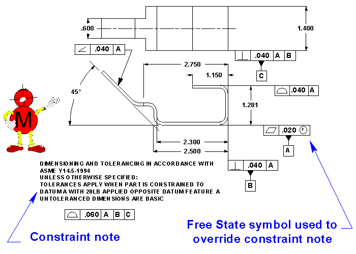
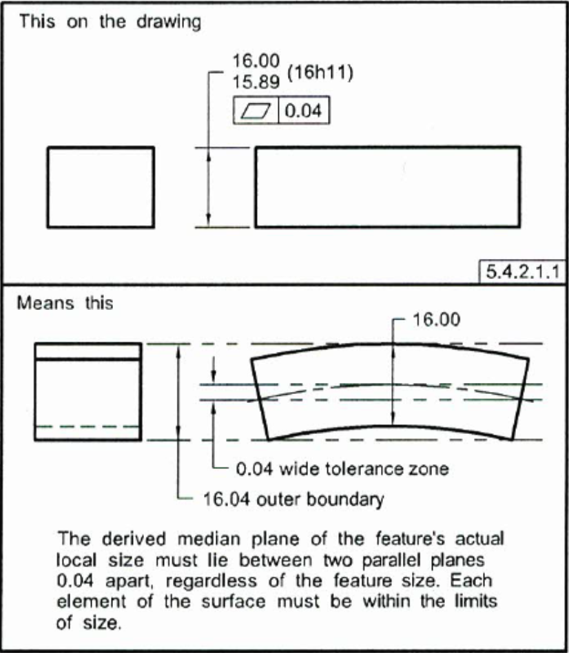
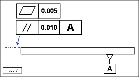
Notation flatness sheet metal drawings.
This makes matching these dimensions during the modeling stage difficult and time consuming.
The most parts in our production line are sheet metal parts.
See document 10 0005 blah drawing drafting standards and practices for the proper setup of a sheet metal drawing.
If you tell them to do 005.
The flat pattern drawing doesn t always list these factors.
My biggest problem with other people s sheet metal drawings is that they use drawing templates designed for machined parts showing standard machining tolerances.
The following practices apply for sheet metal iparts.
If a flat pattern is available in an ipart member file the flat pattern option is enabled in the drawing view dialog.
I want to pull the flat pattern of a sheet metal part into my drawing.
Sheet metal shops can bend to around 015 accuracy.
Requirements for sheet metal part drawings sheet metal parts are typically created from material less than 250 inches thick and are formed by folding the material at specific locations with a controlled bend radius.
Hi i am working on sheet metal part drawing i placed flat pattern on the drawing but didn t show bend line i don t know why i worked sheet metal drawing before it was ok i am using 2012 version.
However to match the other dimensions that are included it would require your manufacturer to work with incorrect or unachievable sheet metal forming factors.
In most cases sheet metal needs to be laser cut water jet or punched prior to bending on a brake therefore a dxf file of the flat pattern of the sheet metal model should be provided.
There is never enough information on the drawings.
These bend notes will describe the bend direction bend angle and bend radius for each bend within solidworks.
When i create the drawing and want to pull in the flat pattern view it comes in folded.
It is also shown folded in the view palette which is not normal.
When you create a drawing view for a sheet metal ipart you can select an explicit ipart member on the model state tab of the drawing view dialog.
Bend notes in your sheet metal part drawings are a clear way to provide the required information for manufacturing they can be automatically inserted into the flat pattern drawing view.
From our experience i can tell you that it is better to make a note with information about bend line bending angle and radii.
The flat pattern view is useful for fabrication and is the only view that supports sheet metal annotations.
I ve done this hundreds of times without issue.
